Anti-Static Coatings: Conductive Chemistry for Electronics & Cleanrooms
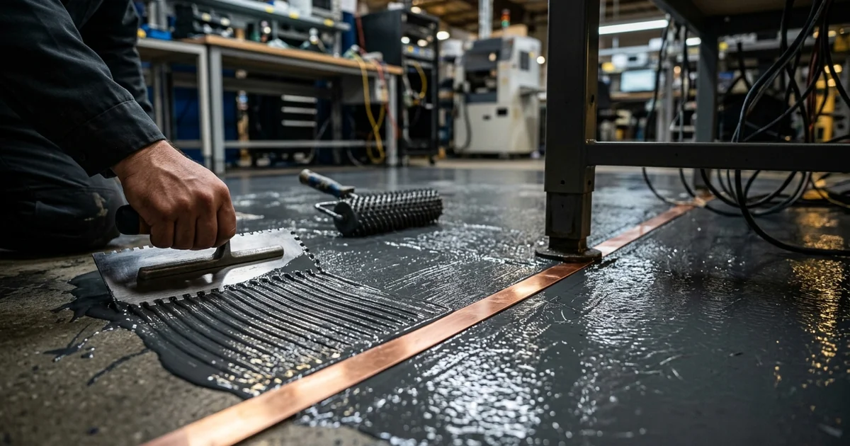
A single electrostatic discharge you never feel can destroy a modern semiconductor device. A few hundred volts is enough — well below the roughly 3,000-volt threshold a person can perceive — and the device may instead take latent damage that fails weeks later in the field. For an electronics manufacturer, that means scrapped boards, warranty returns, and failure investigations that never find a root cause. Anti-static coating chemistry is a primary engineering control against this loss. It gives floors, workbenches, and equipment housings a defined, grounded path that bleeds static charge away before it can build to a damaging level. This guide explains the three chemistries used to make a coating conductive, what the resistance numbers mean, which standards govern an ESD floor, and why the coating is only ever one part of a grounded system. It draws on the same resin and dispersion work we apply across our paints and coatings consulting practice.
Why Static Damage Is Expensive and Hard to Trace
Electrostatic discharge damage is costly precisely because so much of it is invisible at the point it happens. A hard hit punctures a gate oxide or fuses a metal track outright, and the part is dead immediately. A smaller hit leaves the device working but weakened. That second category, latent damage, is the one that drives warranty cost: the part passes end-of-line test and fails in the customer's hands months later with no obvious cause. Controlling static at the floor and bench level is cheaper than chasing those failures backward through a supply chain.
The charge itself comes from ordinary activity on the production floor, and understanding the sources explains why a coating is the right control point:
- Triboelectric charging — two surfaces contacting and separating, such as a person walking across a floor or a part sliding out of a bag, transfers electrons and leaves both surfaces charged
- Field-induced charging — a conductive object sitting in the electric field of a nearby charged surface picks up an induced charge that discharges when it is grounded
- Isolated conductors — a metal fixture or tool that is not bonded to ground holds whatever charge it acquires until something completes the circuit, often through a sensitive device
A conductive or dissipative floor coating tackles the largest and most constant of these sources: people and wheeled equipment moving around. It gives the charge somewhere to go continuously rather than letting it accumulate. That sets up the real question this article answers — how does a layer of pigmented resin become electrically conductive in the first place?
Three Ways a Coating Drains Charge
An ordinary epoxy or polyurethane coating is an electrical insulator, as our paints and coatings formulation guide sets out for standard resin systems. Making one anti-static means deliberately building a charge-transport pathway into a material that does not naturally have one. Three established routes exist, and they differ in how they carry charge, how they behave with humidity, and what they cost. A formulator picks among them based on the target resistance, the appearance the client will accept, and how long the anti-static property has to last. Getting this choice right at the start avoids a coating that tests well on day one and drifts out of range within a season.
- Conductive carbon networks — conductive carbon black, carbon fibre, or graphite is loaded into the resin above its percolation threshold, the concentration at which the particles form a continuous touching network through the film. Charge then moves by electron flow along the carbon pathways to ground. This route is largely humidity-independent and durable, but the film is black or dark grey and filler loading is a sensitive variable.
- Intrinsically conductive polymers (ICPs) — polymers such as PEDOT:PSS and polyaniline conduct through their own conjugated molecular backbone, with no added filler. They allow clear or lightly tinted anti-static coatings, which is why they appear in electronics packaging and display components, but they cost more and some grades have limited stability under UV or heat.
- Migratory ionic additives — hygroscopic species such as quaternary ammonium compounds or ethoxylated amines migrate to the surface and pull a thin water layer from the air, and ions then move through that adsorbed moisture to dissipate charge. This is the lowest-cost route, but it depends on ambient humidity and the additive is gradually lost to cleaning and traffic.
Carbon-filled systems dominate industrial ESD flooring for one reason: the electron-conduction network keeps working at 15% relative humidity just as well as at 60%. The ionic route cannot promise that. Peer-reviewed work on carbon black/epoxy composite coatings describes the same principle. Once a continuous conductive network forms, the coating's surface resistivity is "hardly affected by relative humidity," per research published on PTFE-based antistatic coatings incorporating modified carbon black. That humidity behaviour is the single biggest practical difference between the mechanisms. It leads directly into how the resistance numbers are defined and measured.
Conductive vs Static Dissipative: What the Numbers Mean
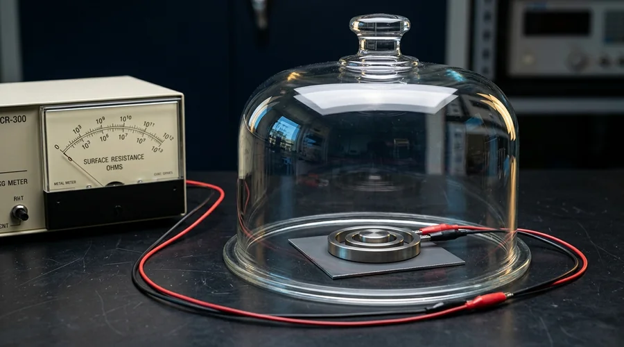
The words "conductive" and "static dissipative" are not marketing labels. They are defined bands on a resistance scale, and a coating is classified by where its measured resistance to ground or point-to-point resistance falls. A static dissipative coating is intentionally more resistive than a conductive one. The slower, more controlled bleed-off limits the peak current during a discharge event and protects the most sensitive devices from a hard, fast dump of charge. Lower resistance is not automatically better; the right band depends on what is being handled. The ranges below reflect the classifications used in ANSI/ESD S7.1 and related standards.
| Class | Typical resistance range | Charge-transport behaviour | Where it is specified |
|---|---|---|---|
| Conductive | Below ~1.0 x 10⁶ Ω to ground | Fast electron flow; charge drains almost immediately | High-throughput assembly, areas with grounded personnel and carts |
| Static dissipative | ~1.0 x 10⁶ to 1.0 x 10⁹ Ω | Controlled, slower bleed-off; limits peak discharge current | Handling of highly ESD-sensitive components; many cleanrooms |
| Anti-static / low-charging | Up to ~1.0 x 10¹¹ Ω | Resists tribocharging but does not reliably ground charge | General-purpose areas, packaging, low-risk zones |
| Insulative (ordinary coating) | Above ~1.0 x 10¹² Ω | No usable charge path; charge accumulates | Not acceptable in an ESD-protected area |
One point causes repeated confusion: an "anti-static" coating in the strict sense only resists generating a charge, while a "conductive" or "dissipative" coating actively removes one. A facility that needs charge grounded should not accept a product sold purely on a low-charging claim. With the target band defined, the next question is which standard sets the pass/fail line and how an installed floor is verified against it.
The Standards That Govern ESD Coatings
An ESD floor is not judged against the coating supplier's data sheet. It is judged against a formal standard the facility has adopted in its ESD control plan. The dominant framework for electronics manufacturing is ANSI/ESD S20.20, which sets system-level requirements, while ANSI/ESD S7.1 defines how the floor's electrical resistance is measured. Knowing which document governs a project changes what the coating has to deliver, because S20.20 tests the floor as part of a grounded system that includes the operator's footwear.
- ANSI/ESD S20.20 — the overarching program standard. For flooring it generally requires resistance to ground below 1.0 x 10⁹ Ω. It also requires the resistance of a person in ESD footwear standing on the floor to stay below the same 1.0 x 10⁹ Ω.
- ANSI/ESD S7.1 — the floor resistance test method, covering point-to-point resistance and resistance-to-ground measurement with defined electrodes, voltages, and conditioning.
- IEC 61340-5-1 — the international equivalent of S20.20, widely referenced outside North America with closely aligned limits.
- Sector overlays — cleanroom, defence, aerospace, and munitions handling often layer additional resistance, outgassing, or documentation requirements on top of the base ESD standard.
The EOS/ESD Association's guidance on static-control flooring makes the same point. The choice between conductive and dissipative flooring follows from the control program. Both are assessed as a walking system, not as a bare coating. That system view is what the final two sections build on.
Anti-Static Coating Chemistry: Formulation Levers and Trade-Offs
Once the mechanism and target band are set, anti-static coating chemistry comes down to a small set of levers. The formulator works them to land the coating inside the specified resistance window and keep it there through service life. Each lever pulls against another property — appearance, mechanical strength, pot life, or cost — so an ESD coating is always a balancing exercise rather than a single optimisation. The levers below are common to the carbon-network route, which is used for most industrial floors. For a broader picture of how these floor systems are built and applied, our two-pack epoxy flooring systems guide and our overview of epoxy coatings both cover the base resin technology an ESD floor is built on.
- Conductive filler type and loading — the dominant lever. Loading has to clear the percolation threshold with margin, because sitting right at the threshold makes resistance swing wildly with small batch or application variations. Too much filler embrittles the film and hurts flow.
- Filler dispersion quality — a poorly dispersed carbon black with agglomerates gives an inconsistent network and patchy resistance across the floor. Dispersion equipment and wetting additives matter as much as the loading number.
- Film thickness and uniformity — resistance to ground depends on the path through the film, so an uneven build produces uneven electrical performance. Self-levelling systems help here.
- Grounding hardware integration — the coating design has to specify how copper grounding strips or a grid are embedded and bonded, because the most conductive film on earth does nothing if it is not tied to ground.
- Topcoat and maintenance chemistry — an insulating wax or floor polish applied later can defeat a conductive floor entirely, so the maintenance regime is part of the specification.
These levers explain why two coatings with the same nominal filler loading can perform differently on the floor. Dispersion, thickness control, and grounding execution separate a floor that holds its specification from one that drifts. That brings the discussion to the most common reason ESD coatings fail in practice.
An ESD Floor Is a Grounded System, Not a Coating
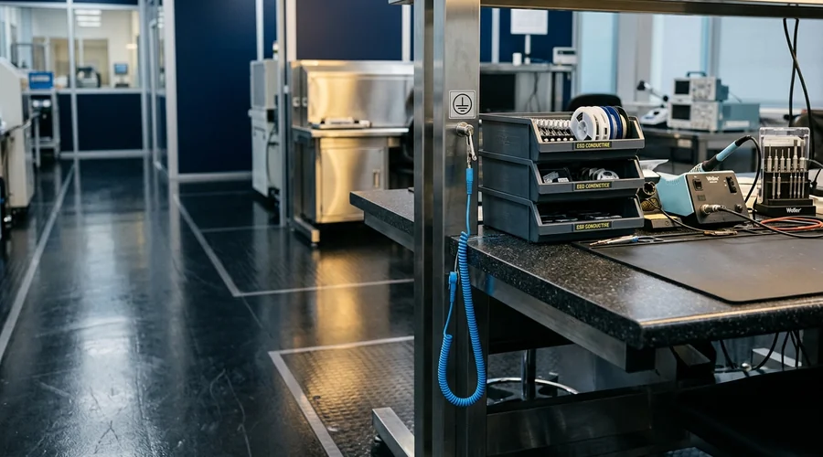
The most frequent field failure of an anti-static coating is not the chemistry. It is a break somewhere in the path between the charged surface and building ground. A conductive coating that is not bonded to ground is just a dark epoxy floor electrically, and an audit measuring resistance to ground will fail it. Treating the installation as a system, with the coating as one component, is what separates a compliant floor from an expensive repaint.
The complete charge path has several links, and every one of them has to be intact:
- The conductive film — correctly formulated, dispersed, and built to a uniform thickness
- The grounding grid or strips — copper conductors embedded in or under the coating on a defined spacing, with enough contact area to the conductive layer
- The bond to building ground — the grounding conductors physically and electrically tied to the facility's equipment-grounding system, not left floating
- The operator interface — ESD footwear or heel straps that connect the person to the floor, since S20.20 tests the person-plus-floor resistance, not the floor alone
- Periodic verification — scheduled retesting of an installed floor, because abrasion, contamination, and additive loss all raise resistance over time
Anti-static coating chemistry gives you a film that can move charge. The installation and the maintenance program are what keep that film connected to ground for years. Scope the project as "specify the whole grounded system" rather than "buy a conductive paint," and you pass the audit the first time. When the target devices are highly sensitive, bringing in ESD-flooring and formulation expertise before the specification is written pays for itself in avoided rework.
Frequently Asked Questions
What is the difference between a conductive coating and a static dissipative coating?
The two terms describe different points on the same electrical resistance scale, and the split is defined by measured resistance, not by chemistry. A conductive coating drains charge quickly and sits at the low-resistance end, generally below about 1.0 x 10⁶ ohms to ground under ANSI/ESD S7.1 test conditions.
A static dissipative coating is deliberately more resistive, typically in the 1.0 x 10⁶ to 1.0 x 10⁹ ohm band, so that charge bleeds away in a controlled, slower way that limits the peak current during a discharge. Which one a facility needs comes from its own ESD control plan and the sensitivity of the devices being handled, not from a general preference for lower resistance.
How does a carbon-filled conductive paint actually move charge?
Conductive carbon black, carbon fibre, or graphite particles are loaded into the resin above a critical concentration called the percolation threshold, the point at which the particles form a continuous touching network through the dry film. Once that network exists, electrons move along the carbon pathways from any charged point on the surface to the grounded substrate or grounding strap.
Below the percolation threshold the particles are isolated islands and the film stays insulating, which is why conductive filler loading is one of the most sensitive variables in the whole formulation. A carbon network conducts by electron flow and is largely unaffected by humidity, unlike the ionic additive route.
Why do some anti-static coatings stop working in dry winter air?
Coatings that rely on migratory ionic additives, such as quaternary ammonium compounds or ethoxylated amines, need a thin adsorbed water layer at the surface to carry charge. The additive is hygroscopic and pulls moisture from the air; ions then move through that surface water film to dissipate static.
When indoor relative humidity drops in winter, the water layer thins and surface resistance climbs, sometimes by orders of magnitude, so the anti-static effect weakens or disappears. Carbon-filled and intrinsically conductive polymer systems do not have this weakness because they conduct through a solid network rather than through adsorbed moisture.
Can I just paint a conductive coating over an ordinary epoxy floor and pass an ESD audit?
Usually not, because ESD flooring is assessed as a grounded system rather than as a coating in isolation. The conductive coating has to be tied to building ground through a properly installed copper grounding strip or grid, and the layer beneath it must not act as an insulating barrier that isolates the conductive film from that ground path.
An audit under ANSI/ESD S20.20 also measures resistance to ground and, for walking tests, the resistance of a person in ESD footwear standing on the floor, so the footwear, the grounding hardware, and the installation all affect the result. A conductive topcoat is necessary but not sufficient on its own.
What resistance range should cleanroom ESD flooring target?
Under ANSI/ESD S20.20, a compliant flooring system generally needs to measure below 1.0 x 10⁹ ohms resistance to ground, and the resistance of a person wearing ESD footwear while standing on the floor also has to stay below 1.0 x 10⁹ ohms. Within that ceiling, many electronics facilities specify a dissipative window of roughly 1.0 x 10⁶ to 1.0 x 10⁹ ohms to keep discharge currents low while still bleeding charge away fast enough.
A cleanroom adds particle-shedding, outgassing, and cleanability constraints on top of the electrical target, so the resin system and filler have to satisfy both sets of requirements at once. The exact numbers belong in the facility's ESD control plan, which should be written before the floor is specified.
Are intrinsically conductive polymers used in real anti-static coatings?
Yes. Intrinsically conductive polymers such as PEDOT:PSS and polyaniline conduct through their own conjugated molecular backbone rather than through an added filler, and they are used where a carbon network would make the coating too dark or too rough. They are common in clear or lightly tinted anti-static topcoats for electronics packaging, display components, and some cleanroom surfaces.
Their trade-offs are cost, sensitivity to processing conditions, and in some grades limited long-term stability under UV or heat, so formulators weigh them against carbon systems case by case rather than treating them as a default.
Does an anti-static coating wear out over time?
It can, and the failure mode depends on the technology. Migratory ionic additives are gradually lost through cleaning, foot traffic, and evaporation, so their surface effect fades over months to a few years and eventually needs recoating or replacement.
Carbon-filled and intrinsically conductive polymer coatings are more durable electrically because the conductive phase is bound into the film, but abrasion that removes coating thickness, or contamination that coats the surface, can still raise resistance over time. This is why ANSI/ESD S20.20 requires periodic verification testing of an installed floor rather than a one-time acceptance test.
Specifying an ESD Floor or Anti-Static Coating?
Global Formulation provides paints and coatings consultancy — conductive filler selection, dispersion and percolation control, ESD standard compliance, and grounded-system specification for electronics and cleanroom facilities.
Talk to Our Formulation Team