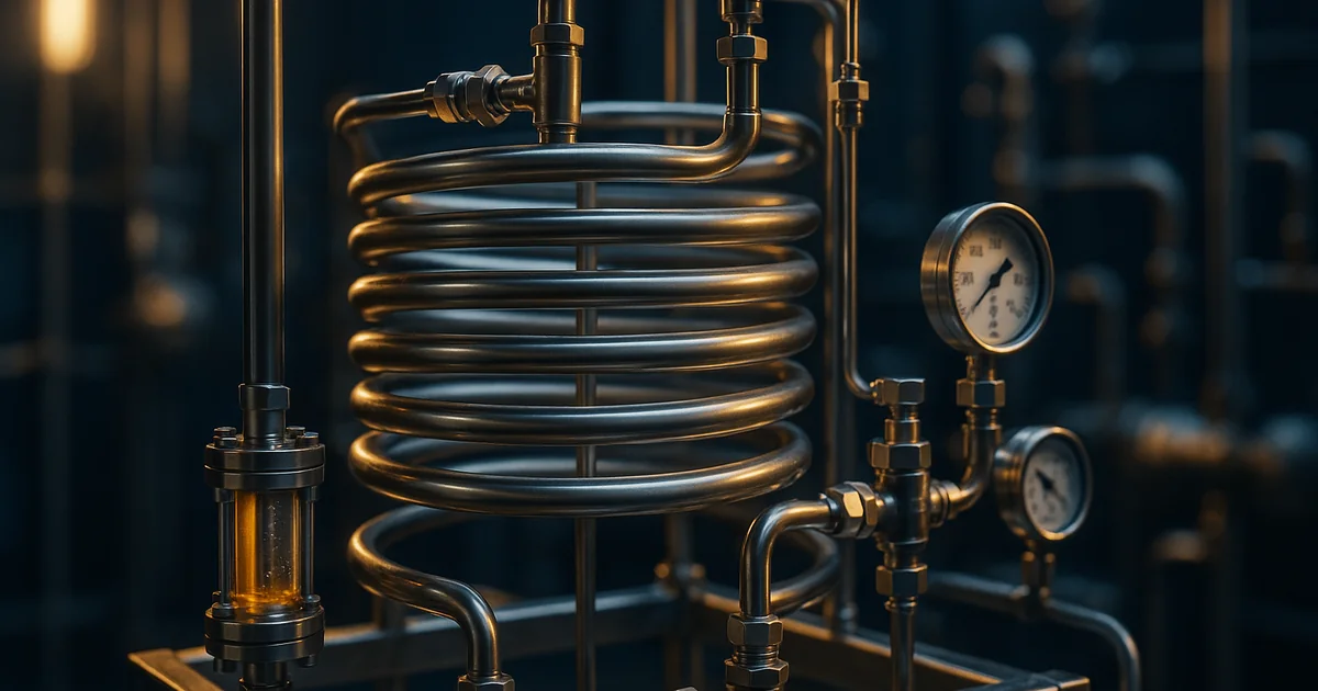
A process chemist moving a reaction from batch to continuous production usually reaches for a stirred tank first, because it looks like the batch reactor they already trust. That instinct is often wrong. The choice between a continuous stirred tank reactor (CSTR) and a plug flow reactor (PFR) sets the conversion you can reach in a given volume, the selectivity you keep between competing reactions, and how much the reactor costs to build and cool. Get this decision wrong early and every downstream sizing calculation inherits the error — a plant commissioned around the wrong reactor type rarely gets a second chance to be right. This guide compares CSTR vs PFR on the mechanisms that actually decide performance, shows when a cascade of tanks closes the gap to plug flow, and gives a practical framework for choosing between them. It reflects how we approach reactor selection in our chemical reaction engineering work before a continuous process is specified.
Why This Choice Comes Before Reactor Sizing
Continuous manufacturing is not one reactor type — it is a spectrum bounded by two ideal cases, and every real continuous reactor sits somewhere between them. Get the mental model wrong and every equation that follows, from residence time to jacket area, is built on the wrong foundation. The CSTR and the PFR are the two textbook extremes engineers reason from, even though neither exists in pure form on a real plant floor.
The two ideal models make opposite assumptions about mixing:
- The CSTR assumes the vessel is perfectly mixed, so composition and temperature are uniform throughout and identical to the outlet stream at every instant.
- The PFR assumes fluid moves through as ordered slices with zero mixing along the direction of flow, so each slice reacts independently as it travels, like a batch reactor riding a conveyor belt.
- Real reactors approximate one or the other — a well-agitated tank behaves close to a CSTR; a long, narrow tube in turbulent flow behaves close to a PFR; a packed bed or a poorly agitated tank sits somewhere in between.
This matters commercially before it matters technically. A continuous line built around the wrong idealisation under-converts, over-produces an impurity, or needs a second reactor bolted on to fix what the first one couldn't do. The mechanism behind that gap is the subject of the next section, and it comes down to one thing: what concentration the reacting fluid actually experiences.
How a CSTR and a PFR Actually Differ
The entire performance gap between these two reactors reduces to one variable: the concentration the reacting fluid sees over its residence time. Everything else — conversion, selectivity, heat load distribution — follows from that single difference. Understanding it makes the rest of the comparison a matter of consequence, not memorisation.
In a CSTR, feed entering the vessel is instantly diluted into the bulk fluid already present. The reactor operates at a single, uniform concentration — the outlet concentration — for its entire volume and its entire residence time. If the reaction rate depends on concentration, as almost all do, the CSTR runs at the lowest rate on the whole conversion curve, all the time. In a PFR, no such dilution happens. A slice of fluid entering at the feed concentration reacts as it travels, so concentration falls continuously along the tube's length. Early in the tube the concentration — and therefore the rate — is high; only near the outlet does it approach the CSTR's operating point.
The design equations formalise this. For a CSTR, the reactor volume is the outlet flow rate multiplied by the residence time needed at the outlet rate. For a PFR, the volume is found by integrating the inverse rate over the whole conversion range, from feed to outlet. That integral is why PFR sizing always uses less volume than CSTR sizing for the same conversion target, whenever the rate falls as conversion rises — which is the normal case for a positive-order reaction.
This concentration-history difference is not an abstraction — it is what a residence time distribution (RTD) measurement actually detects, and it is the mechanism behind every conversion and selectivity difference discussed next.
The whole CSTR-vs-PFR comparison in one curve: the CSTR spends its entire volume at C_out, the PFR spends most of its length above it.
Conversion and Selectivity Compared
Two consequences follow directly from the concentration-history difference, and they are the two numbers a technical director actually cares about: how much product you get out, and how clean it is. Both trace back to the same mechanism, so understanding one makes the other intuitive.
Conversion. For any reaction with positive-order kinetics, a PFR reaches higher conversion than a CSTR of equal volume at equal residence time — equivalently, a PFR needs less volume than a CSTR for the same target conversion. The gap widens as reaction order increases and as target conversion rises toward completion, because the CSTR's constant low-concentration operation becomes proportionally more punishing the closer you push toward full conversion. For a zero-order reaction the two reactors are identical, since the rate does not depend on concentration and the concentration history is irrelevant.
Selectivity. When a desired reaction competes with an unwanted parallel or series reaction, the reactor type can matter more than the catalyst. A CSTR's low, constant concentration favours a competing reaction of lower order relative to the desired one — this is exploited deliberately, for example, when a low steady concentration suppresses an unwanted higher-order side reaction. A PFR's high concentration early in the tube favours the opposite case. There is no universally "better" reactor for selectivity — the answer depends on the relative reaction orders and rate constants of the desired and undesired pathways, and getting this wrong is a documented cause of selectivity loss when a process moves from lab to plant.
- Series reactions (A → B → C, B wanted) — a PFR generally gives a better yield of the intermediate B, because it avoids over-exposing already-formed B to further reaction in a well-mixed pool.
- Parallel reactions of different order competing for the same reactant — the lower-concentration environment of a CSTR favours whichever pathway has the lower reaction order relative to the limiting reactant.
- Autocatalytic reactions — a CSTR can outperform a PFR, because the bulk already contains product that accelerates the reaction from the moment feed enters, avoiding the slow initial induction period a PFR experiences at its inlet.
Conversion and selectivity rarely point the same direction, which is exactly why reactor selection is a trade-off decision and not a lookup table. That trade-off is easiest to see side by side, which the next section lays out directly.
CSTR vs PFR: Side-by-Side Comparison
Putting the mechanism, the performance consequence, and the practical operating reality in one table makes the trade-off concrete. Use this as a first filter before running the actual sizing calculation for a specific reaction and target conversion.
| Attribute | CSTR | PFR |
|---|---|---|
| Mixing assumption | Perfect, uniform throughout | None along the flow direction |
| Concentration profile | Flat, at outlet value everywhere | Falls continuously from inlet to outlet |
| Volume for given conversion | Larger, for positive-order kinetics | Smaller, for positive-order kinetics |
| Temperature control | Easier — one well-mixed zone to cool | Harder — hot spots possible along the tube for exothermic reactions |
| Solids and slurries | Tolerates suspended solids well | Prone to plugging and channelling |
| Residence time distribution | Wide — some fluid exits almost immediately, some stays much longer | Narrow — ideally, every element has the same residence time |
| Sampling and monitoring | Simple — outlet equals internal composition | Position-dependent — needs sampling along the length to see the profile |
| Best suited to | Autocatalytic reactions, selectivity via dilution, solids-bearing feeds | High single-pass conversion, series reactions favouring an intermediate, fast reactions with tight heat control via small tube diameter |
Most real chemistries do not sit cleanly at either extreme, and the practical answer for a plant is frequently a hybrid, not a pure choice. The next section covers the most common hybrid: a cascade of tanks built specifically to close the gap to plug flow.
CSTR Cascades: Approaching Plug Flow
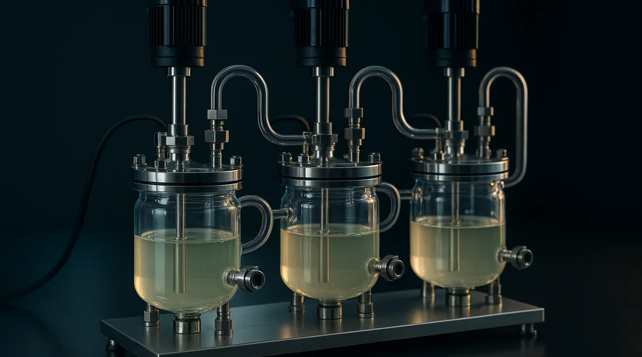
A single CSTR gives up volume efficiency for operability. A cascade of CSTRs in series recovers much of that lost efficiency while keeping the practical advantages — easy solids handling, simple temperature control per stage — that make tanks attractive in the first place. This is the reactor configuration most specialty chemical plants actually build when they want continuous production without the plugging risk of a long tube.
The tanks-in-series model is the standard framework for this, and it is treated as core reaction engineering curriculum by professional bodies such as the American Institute of Chemical Engineers. It treats a real reactor's residence time distribution as equivalent to N ideal CSTRs of equal volume in series, using N as a single fitted parameter. As N increases, the residence time distribution narrows and the cascade's performance approaches that of an ideal PFR of the same total volume; as N approaches infinity, the two become mathematically identical. In practice:
- One CSTR gives the widest residence time distribution and the largest volume penalty relative to a PFR.
- Three to five tanks in series recover most of the practical conversion gap for typical first-order and second-order specialty chemistry, and is the range most commonly built.
- Beyond about eight to ten tanks, further stages bring diminishing returns relative to their added capital and complexity — at that point a true tubular reactor usually becomes the more economic choice.
A cascade converts the CSTR-vs-PFR choice from binary into a design variable — the number of stages — that can be tuned against capital cost, plugging risk, and the conversion target. That framing carries directly into how the choice gets made for an actual process, which is the practical question the rest of this article answers.
Choosing Between Them for a Real Process
Reactor selection in practice is rarely a pure kinetics argument — it is a short list of practical constraints that eliminate options faster than any equation does. Working through them in order, before reaching for a design equation, saves a great deal of wasted sizing work on a configuration that was never going to survive contact with the actual feed stream.
- Feed physical form — a feed containing suspended solids, a slurry, or a viscous stream rules out a narrow tubular PFR quickly; a stirred tank tolerates these far better. This is the same consideration behind reactor configuration selection for batch and semi-batch processes.
- Heat release rate — a strongly exothermic reaction in a long single tube risks a travelling hot spot with no way to intervene locally; a jacketed CSTR cascade, or a PFR built from many short cooled segments, manages this more safely.
- Required single-pass conversion — a target above roughly 90–95% strongly favours a PFR or a large cascade, since a single CSTR needs disproportionately more volume to approach complete conversion.
- Selectivity requirement — identify which pathway (desired or undesired) has the higher reaction order, and choose the concentration profile — flat and low for a CSTR, high-to-low for a PFR — that disadvantages the undesired one.
- Turndown and campaign flexibility — a CSTR cascade generally tolerates a wider flow range without a major change in performance than a fixed-geometry tubular reactor does.
- Existing assets — a plant with jacketed stirred tanks already installed has a strong economic pull toward a CSTR cascade over a purpose-built tubular system, regardless of which is technically ideal.
None of these constraints are absolute, and the final answer is usually a specific hybrid — a short cascade feeding a tubular finishing reactor, or a tube followed by a stirred hold tank — rather than a textbook-pure choice. Even after that decision is made, however, a continuous reactor rarely performs to its ideal model on day one, and the gap between the two shows up as one of a small number of recognisable symptoms.
Troubleshooting Continuous Reactor Performance
When a commissioned continuous reactor underperforms its design conversion, the fault almost always traces back to the real vessel deviating from the ideal model it was sized against. Diagnosing which deviation is at fault is a residence-time-distribution problem before it is a kinetics problem, and the symptoms below are the standard patterns worth checking first.
- Low conversion in a continuous reactor — commonly caused by short-circuiting or bypassing in a poorly baffled CSTR, or by a shorter effective residence time than designed because of unaccounted holdup volume, such as a dip pipe or a poorly swept corner.
- Poor selectivity in a tubular reactor — often traces to a laminar rather than turbulent velocity profile, which broadens the residence time distribution far beyond the ideal plug flow assumption and lets some fluid over-react while other fluid under-reacts.
- Channelling in a tubular or packed reactor — uneven packing density, a poor inlet flow distributor, or a small tube-to-particle diameter ratio in a fixed bed creates a fast path that bypasses much of the intended contact time.
- Hot spot travelling along a tubular reactor — a strongly exothermic reaction concentrated near the inlet outpaces the cooling jacket's local capacity; the fix is usually staged cooling zones or a lower inlet concentration via dilution or split feed.
- Inconsistent performance across a CSTR cascade — one stage receiving disproportionate flow through an unbalanced overflow or transfer line effectively removes a stage from the cascade, widening the residence time distribution back toward single-tank behaviour.
A pulse or step tracer study remains the definitive diagnostic for every one of these symptoms, because it measures the actual residence time distribution rather than the one assumed at design — a method documented in process design guidance published by the Institution of Chemical Engineers. Reactor pressure boundary design for either configuration also falls under the ASME Boiler and Pressure Vessel Code, which governs the mechanical design of both stirred tanks and tubular reactor coils regardless of which flow model they approximate. Our companion guide on catalyst behaviour in continuous reactors covers a related failure mode worth ruling out when a fixed-bed PFR underperforms — declining catalyst activity along the bed length rather than a mixing problem. On the plant side, jacket and cascade temperature stability is covered in our guide to cascade temperature control for jacketed reactors, which addresses the control-loop half of keeping a multi-stage CSTR train stable.
Getting the reactor type right at the concept stage avoids most of this troubleshooting altogether — which is why the decision belongs at the very start of a continuous manufacturing project, not after the skid is welded. Manufacturers scaling specialty chemical production in India, the Gulf and Southeast Asia increasingly evaluate this choice formally before committing capital, because retrofitting a tubular reactor into a plant built around tanks — or the reverse — is materially more expensive than specifying correctly the first time. If you are evaluating a move from batch to continuous production, our scale-up and process development service covers reactor selection, residence time distribution studies and the cascade design work this decision depends on.
Frequently Asked Questions
What is the difference between a CSTR and a PFR?
A continuous stirred tank reactor (CSTR) is a well-mixed vessel where feed entering is instantly diluted into the bulk, so the reaction runs at the low, outlet concentration throughout the vessel. A plug flow reactor (PFR) is a tube where fluid moves through in ordered slices with no back-mixing, so concentration falls continuously along its length and most of the volume sees a higher concentration than the CSTR ever does.
That single difference in concentration history is why the two give different conversion, selectivity, and heat-management behaviour for the same reaction and the same residence time.
Which reactor gives higher conversion, a CSTR or a PFR?
For any reaction with kinetics of positive order, a PFR reaches a higher conversion than a single CSTR of the same volume operating at the same residence time. The CSTR runs its entire volume at the diluted outlet concentration, which is the slowest point on the rate curve, while the PFR spends most of its length at a higher concentration and therefore a higher rate.
The gap widens as reaction order increases. For a zero-order reaction the two are identical, because the rate does not depend on concentration at all.
When is a CSTR better than a PFR?
A CSTR is the better choice when the reaction is autocatalytic, when a low steady concentration suppresses an unwanted side reaction, when reliable temperature control matters more than absolute conversion, when the feed contains solids or a slurry that would settle or plug a narrow tube, or when a single well-mixed vessel is simpler to operate and clean between campaigns.
A CSTR is also easier to instrument and troubleshoot, because its outlet composition equals its internal composition, so a single sample point tells you what the whole reactor is doing.
How many CSTRs in series are equivalent to a PFR?
A cascade of CSTRs approaches PFR performance as the number of tanks increases, because each additional stage narrows the residence time distribution and reduces back-mixing. In practice three to five well-sized tanks in series recover most of the conversion gap for a first-order reaction, and further tanks bring diminishing returns.
The tanks-in-series model formalises this: it treats a real reactor's residence time distribution as N ideal CSTRs in series and uses N as a single parameter describing how close the real vessel sits to plug flow.
Why is a PFR more efficient than a CSTR for the same volume?
A PFR is more volume-efficient because every element of fluid experiences the full concentration history from feed to outlet, spending time at high concentration where the rate is fast. A CSTR instantly dilutes incoming feed into the bulk, so the entire vessel operates at the lowest concentration in the process.
Integrating the rate expression over each reactor's concentration profile shows the PFR needs less volume than a CSTR to reach the same conversion, for any reaction order greater than zero. This is a direct, quantifiable consequence of the two reactors' different residence time distributions, not a rule of thumb.
Can a plug flow reactor be run as a batch reactor?
An ideal PFR and an ideal batch reactor obey the same design equation once time and axial position are treated as equivalent variables — a fluid element travelling along a PFR sees the same concentration history as a batch charge held for the equivalent residence time.
This equivalence is why kinetic data measured in a batch flask can be used directly to size a continuous tubular reactor, provided the flow in the tube is genuinely close to plug flow and not laminar with a parabolic velocity profile that broadens the residence time distribution.
What causes channelling in a tubular reactor?
Channelling occurs when part of the cross-section of a tubular or packed reactor carries disproportionately more flow than the rest, creating a fast path that bypasses the intended residence time while other regions become stagnant.
Common causes include uneven packing density in a fixed-bed reactor, poor inlet flow distribution, wall effects in tubes with a small tube-to-particle diameter ratio, and laminar flow with its parabolic velocity profile. A tracer study measuring the residence time distribution is the standard diagnostic, since channelling shows up as an early breakthrough peak followed by a long tail.
Evaluating a Move to Continuous Production?
Global Formulation provides route selection, reactor design and scale-up partnership for continuous manufacturing — choosing between CSTR, PFR and cascade configurations, sizing against your actual kinetics, and building a technology transfer package that holds on the first campaign.
Talk to Our Process Team