Electric Vehicle Fluids: e-Axle Lubricants and Cooling
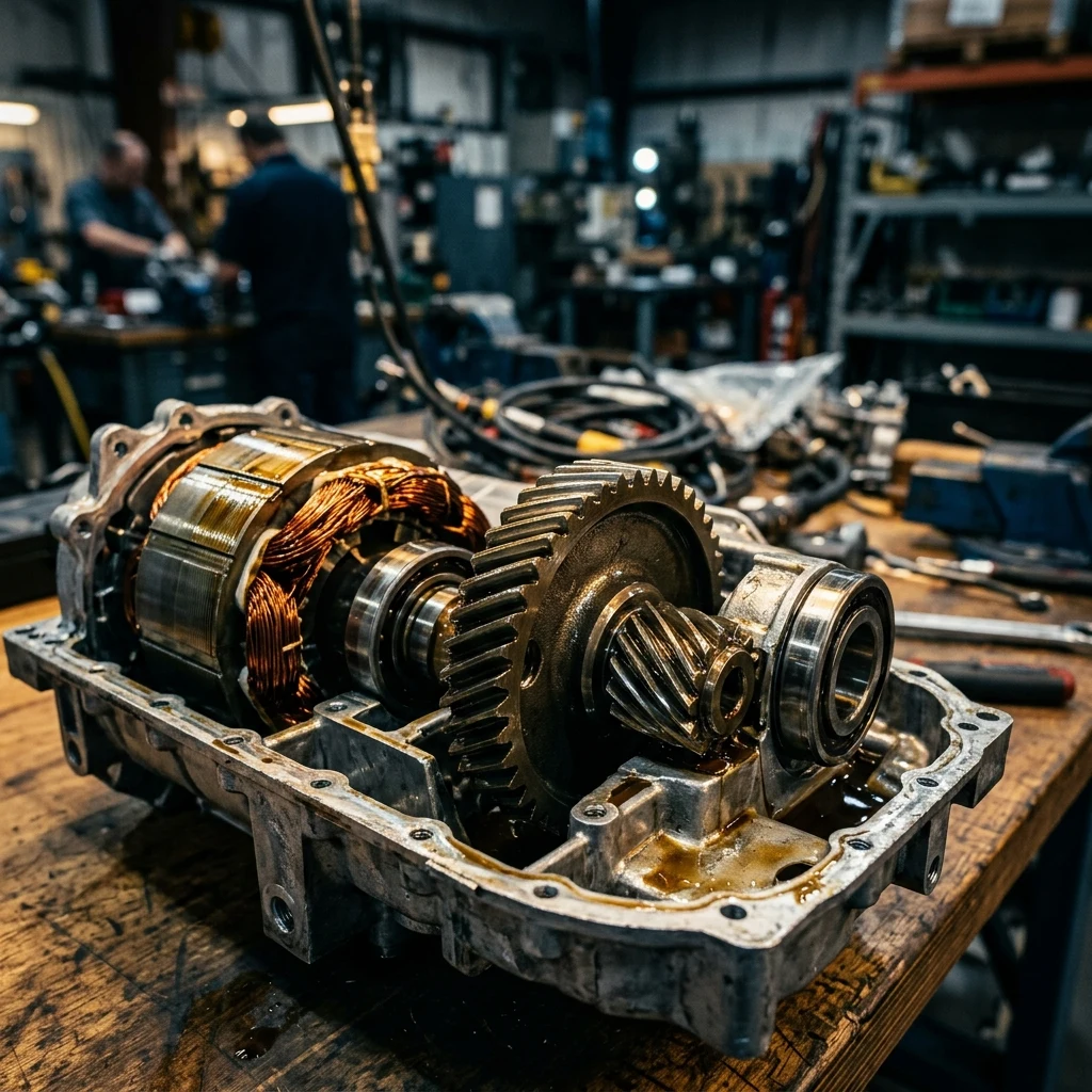
A lubricant blender who has spent twenty years perfecting gear oils and automatic transmission fluids can walk into an electric drivetrain programme and discover that most of that hard-won additive knowledge is now a liability. Electric vehicle fluids and lubricants operate in an environment that has no combustion, no clutches, and no hydraulic control circuit — but does have exposed copper windings, inverter-driven electrical noise, and a motor that delivers maximum torque the instant it starts turning. Get the chemistry wrong and the failure does not show up as a worn gear tooth; it shows up as degraded winding insulation or a drive unit that quietly loses efficiency. This guide covers what actually separates an e-axle fluid from a transmission fluid, why electrical properties now sit alongside viscosity as a primary design parameter, how battery thermal management fluids differ from driveline fluids, and what a validation programme has to prove before a fill-for-life claim is defensible. It is written for formulators, blenders, and manufacturers moving into electric drivetrain fluids from a conventional lubricants background.
Why Electric Vehicle Fluids and Lubricants Are a Different Problem
The instinct when a new drivetrain arrives is to reach for the closest existing product and adjust the viscosity. That instinct fails badly with electric drive units, because the change is not a matter of degree — the entire set of degradation mechanisms a fluid has to survive has been replaced with a different set. Understanding what disappeared and what took its place is the starting point for every downstream formulation decision.
Removing combustion removes the dominant contamination pathways that shaped engine and driveline lubricant design for a century. There is no fuel dilution thinning the fluid, no soot loading it with abrasive carbon, and no acidic blow-by products demanding a reserve of alkalinity to neutralise. What replaces them is an electrical environment: a fluid that may be in direct contact with copper windings, an inverter switching at high frequency nearby, and thermal loads concentrated in a compact housing that also contains a reduction gearset spinning far faster than any internal combustion engine crankshaft ever did.
| Design Driver | Conventional ATF / Gear Oil | Electric Drive Unit Fluid |
|---|---|---|
| Primary contamination | Fuel dilution, soot, combustion acids | Wear debris, moisture, oxidation only |
| Friction requirement | Wet clutch and synchroniser friction control | No friction modification requirement |
| Electrical properties | Not specified | Resistivity and breakdown voltage specified |
| Copper exposure | Limited bushings and synchroniser rings | Large winding and conductor surface area |
| Peak torque condition | Rises with engine speed | Full torque available from standstill |
| Cooling duty | Bulk heat removal from gear mesh | Direct heat removal from motor windings |
That table is the reason electric drive fluids have become a distinct product category rather than a viscosity variant of an existing line, and the sharpest version of the problem appears in the integrated e-axle.
Inside the e-Axle: One Fluid Doing Three Jobs
An e-axle integrates the electric motor, a reduction gearset, and in many designs the power electronics into a single sealed housing served by one fluid circuit. That packaging decision is what makes e-axle fluid formulation genuinely difficult: a single chemistry has to satisfy three requirement sets that pull against each other, and no one of them can be optimised at the expense of the other two. Every trade-off in the formulation traces back to this architectural choice.
The three duties the fluid carries simultaneously are distinct engineering problems with different ideal solutions:
- Gear and bearing lubrication — Protecting the reduction gearset against scuffing and micropitting under peak torque, and supporting bearings running at speeds well above conventional automotive practice
- Heat transfer — Carrying heat away from motor windings and, in many architectures, spraying or splashing directly onto the stator end windings and rotor
- Electrical insulation — Remaining a reliable dielectric across the full operating temperature range, in continuous contact with live conductors and insulation materials
The conflict is immediate. Classic load-carrying chemistry — sulfur-phosphorus extreme pressure additives and zinc dialkyldithiophosphate — earns its gear protection by reacting chemically with metal surfaces, and copper is one of the metals it reacts with. In a conventional gearbox the amount of exposed copper is small enough to manage. In an e-axle the fluid is washing over windings and conductors continuously, so the additive system that would give the best gear protection is also the one most likely to attack the electrical system the drive unit depends on. Formulators working from a conventional gear oil formulation baseline have to rebuild load protection from chemistries that clear copper corrosion testing, and the search for alternatives to conventional ZDDP antiwear chemistry is one of the most active areas in driveline lubricant development.
Resolving the additive conflict still leaves the requirement that has no precedent at all in conventional driveline practice: proving the fluid behaves as an insulator under real operating conditions.
Dielectric EV Fluid: The Electrical Requirements
For the first time in mainstream automotive lubrication, a fluid has to be specified as an electrical component. A fluid that circulates through a motor is part of the insulation system whether the formulator treats it that way or not, and its electrical behaviour has to be characterised with the same rigour applied to viscosity or oxidation stability. Two measured properties dominate that characterisation.

Volume resistivity measures how strongly the fluid resists carrying current, while dielectric strength describes the field intensity at which it stops insulating and breaks down. Both are measured by established methods — breakdown voltage under ASTM D877 and ASTM D1816, and permittivity, dissipation factor, and resistivity under ASTM D924 — and both have to be evaluated across the whole operating temperature range. This last point catches teams out repeatedly. Resistivity falls as temperature climbs and collapses in the presence of dissolved water, so a fluid that measures comfortably within specification on a bench at ambient conditions can be far outside it at the winding temperatures a hard-worked motor reaches.
The other electrical phenomenon that shapes drive unit design is bearing current damage. Inverters switch voltage at high frequency, producing a common-mode voltage that can appear across the motor shaft; when it exceeds what the lubricant film in a rolling element bearing can withstand, it discharges through the rolling contact and erodes the raceway, leaving the frosted and fluted surfaces long documented in inverter-driven industrial motors. The countermeasures are hardware-level — shaft grounding rings, insulated bearings, and hybrid bearings with non-conducting ceramic rolling elements — so while the fluid's electrical properties are specified as part of the system, bearing protection is engineered into the drive unit rather than delegated to the lubricant.
Electrical specification governs the fluid inside the drive unit, but the largest thermal load in an electric vehicle sits elsewhere — in the battery pack, where an entirely different fluid strategy applies.
EV Battery Coolant Chemistry and Thermal Management
Battery thermal management is a separate engineering discipline from driveline lubrication, and the fluids serving it answer to different physics. Lithium-ion cells have a narrow temperature band in which they charge quickly, deliver full power, and age slowly, and holding them inside that band under fast charging is one of the harder problems in vehicle engineering. Two fluid strategies dominate, and they resolve the same problem in opposite directions.
Indirect cooling with a water-glycol mixture circulating through aluminium cold plates remains the mainstream production approach. Water-glycol has a far higher specific heat capacity than any oil-based fluid and a low viscosity that keeps pumping losses down, so it moves a great deal of heat for the mass circulated. Its inhibitor package matters more than in a conventional engine cooling circuit because these systems are aluminium-intensive, and the corrosion chemistry has to be built around that. The unavoidable limitation is that water-glycol conducts electricity, so it must be kept strictly separated from cells and busbars — heat has to travel through the cold plate wall and a thermal interface material, and any internal leak becomes an electrical fault rather than a maintenance issue.
Direct immersion cooling inverts the trade. A dielectric fluid can wet the cell surface itself, which removes the thermal resistance of the cold plate and the interface material and puts the coolant in contact with the heat source. Because the fluid does not conduct, a leak inside the pack is no longer a short-circuit event, and the improved thermal contact is relevant to how a pack behaves during thermal runaway. The costs are real: dielectric fluids carry less heat per unit mass, add fluid weight to the pack, cost considerably more per litre, and demand a far broader material compatibility programme covering every polymer, seal, and adhesive inside the enclosure.
| Property | Water-Glycol Indirect Cooling | Dielectric Immersion Cooling |
|---|---|---|
| Specific heat capacity | High | Lower |
| Electrical conductivity | Conductive — must be isolated | Insulating — direct cell contact permitted |
| Thermal path to cell | Through cold plate and interface material | Direct contact with cell surface |
| Leak consequence | Potential short circuit | No electrical fault path |
| Fluid mass and cost | Low | Higher on both counts |
| Production maturity | Dominant in current packs | Emerging, programme-specific |
Choosing between the two is a pack-architecture decision rather than a fluid decision, driven by charging power targets and the mass and cost budget available — but whichever fluid touches the hardware, it has to prove it will not degrade the materials it contacts.
e-Motor Lubricant Compatibility: Copper, Enamel and Elastomers
Material compatibility testing in a conventional gearbox programme is a short list dominated by seals and a copper strip. In an electric drive unit the list expands to include the entire electrical insulation system, and a fluid that passes every tribological test can still be rejected because it softened a winding varnish. This is the stage where promising e-axle candidates most often fail, and it is worth building the test matrix before the formulation work rather than after.
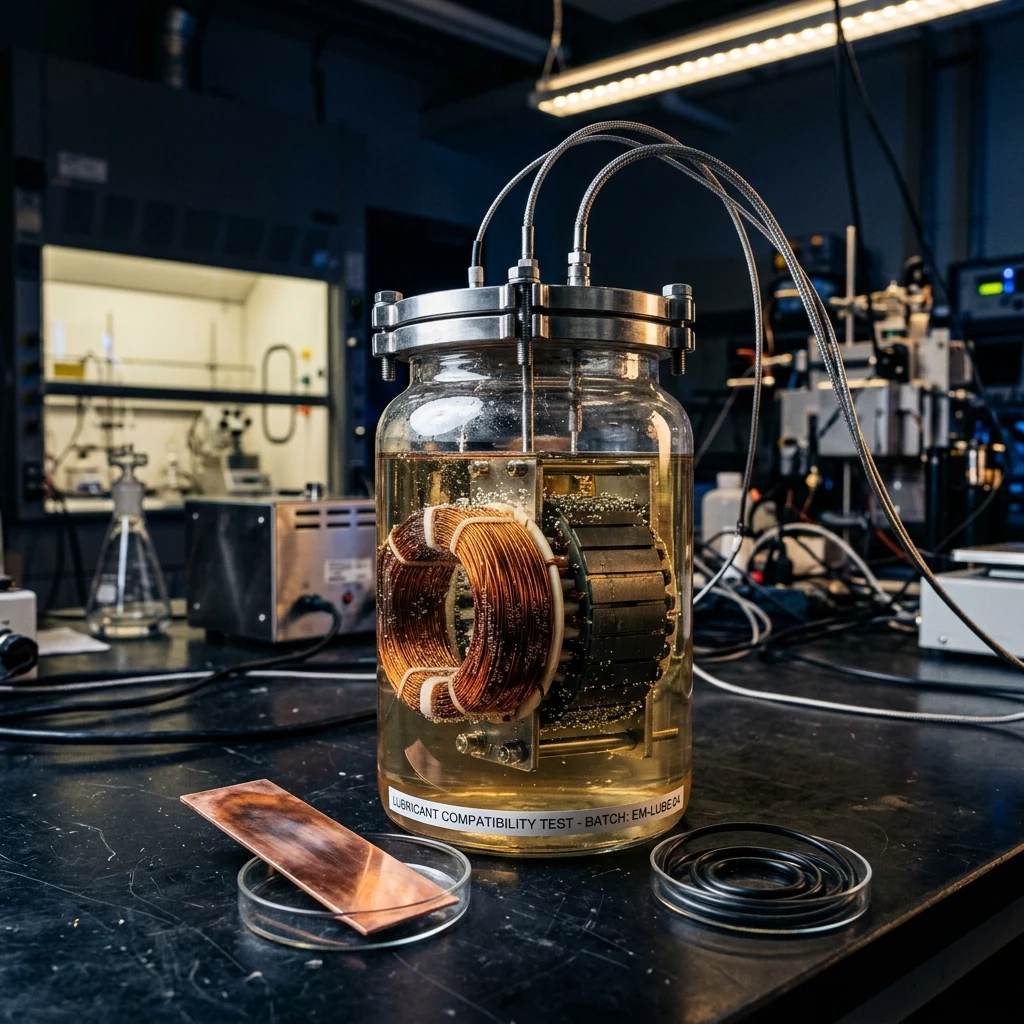
A representative compatibility matrix for an electric drive fluid covers the following material families, each of which fails in a different way:
- Bare copper and conductor joints — Screened by copper strip corrosion testing under ASTM D130, which remains the first gate any candidate additive package has to clear
- Magnet wire enamel — Polyester-imide and polyamide-imide coatings assessed by immersion ageing, then checked for retained breakdown voltage, adhesion, and flexibility rather than appearance alone
- Impregnating varnish and resin — Evaluated for softening, swelling, and extraction of components into the fluid, any of which weakens the mechanical bracing of the windings
- Slot liners and insulation papers — Aramid-based materials checked for dimensional stability and retained dielectric performance after prolonged hot fluid exposure
- Elastomer seals — Fluoroelastomer, hydrogenated nitrile, and silicone grades tested for volume swell, hardness change, and retained sealing force at operating temperature
Two points separate this from conventional compatibility work. First, the pass criteria are electrical as well as physical: a varnish that shows no visible change but has lost breakdown voltage has failed. Second, ageing matters more than the fresh-fluid result, because additive degradation products, not the virgin additives, are frequently what attacks the insulation. Base fluid choice feeds directly into this, which is why the base oil group selected for the formulation is decided alongside the additive system rather than before it.
Clearing the compatibility matrix produces a fluid that will not damage the drive unit — the remaining question is whether it also makes the vehicle efficient enough to justify itself.
Viscosity, Efficiency and Validation Testing
Every litre of fluid in an electric drive unit is a parasitic load the battery has to pay for, and unlike an engine that idles and coasts, an electric drive unit rotates continuously whenever the vehicle moves. Small efficiency differences therefore accumulate across the entire drive cycle and show up directly in range figures. That economic pressure pushes viscosity down, and something has to push back.
What pushes back is film thickness at the gear mesh. An electric motor delivers peak torque from a standing start, so the reduction gearset experiences its highest contact stress at low sliding speed — precisely the condition in which a hydrodynamic film is hardest to build and maintain. Thinning the fluid to chase churning and windage losses erodes the margin protecting the gear flanks under exactly the load case the drivetrain is designed to deliver. This trade cannot be resolved from a viscosity chart; it has to be validated on the real gear geometry and the real duty cycle.
A validation programme for an electric drive fluid typically spans the following:
- Load-carrying and wear testing — Gear scuffing and micropitting evaluation on the target geometry, plus bearing testing at the high speeds the motor actually reaches
- Copper and material compatibility — ASTM D130 copper corrosion plus the full insulation-system matrix, run on aged fluid as well as fresh
- Electrical characterisation — Volume resistivity, breakdown voltage under ASTM D877 or ASTM D1816, and conductivity under ASTM D2624, measured across the temperature range
- Foam and air release — Foaming tendency under ASTM D892 and D6082 and air release under ASTM D3427, which matter far more than in a conventional gearbox because high-rotor-speed fluid churning aerates aggressively and entrained air destroys both film strength and heat transfer
- Oxidation and long-duration ageing — Extended thermal ageing tracking viscosity, oxidation, wear metals, and the drift of electrical properties over time
One structural difference is worth naming plainly: there is no settled industry-wide specification for electric drive fluids comparable to the established transmission and gear oil standards, so requirements are set programme by programme by the vehicle manufacturer. For a blender entering this market, that means qualification is a direct technical engagement with the customer rather than a certificate obtained once and applied broadly — the same shift in commercial model that reshaped modern lubricant formulation and technology as OEM specifications displaced generic categories.
Frequently Asked Questions
What is an e-axle fluid, and how is it different from automatic transmission fluid?
An e-axle fluid is the single fluid used in an integrated electric drive unit, where the electric motor, a reduction gearset, and often the power electronics share one housing and one lubrication circuit. Unlike an automatic transmission fluid, which is engineered around wet clutch friction behaviour, torque converter operation, and hydraulic control of shift elements, an e-axle fluid has no clutches or hydraulic control system to serve at all.
Instead it has to lubricate high-speed bearings and reduction gears, carry heat away from motor windings it may contact directly, and remain electrically insulating across the full operating temperature range. That last requirement has no equivalent in conventional transmission fluid, which is why an existing automatic transmission fluid cannot simply be relabelled for electric drive service even when its viscosity grade looks appropriate on paper.
Why can conventional extreme pressure and antiwear additives not be used in EV driveline fluids?
Traditional extreme pressure and antiwear packages rely heavily on sulfur-phosphorus chemistry and zinc dialkyldithiophosphate, both of which protect surfaces by reacting with metal under load to form a sacrificial film. The difficulty in an electric drive unit is that these same chemistries are aggressive toward copper and other yellow metals, and an integrated e-axle exposes the fluid to a large surface area of copper windings, bar conductors, and joined connections.
Copper attack in this environment is not a cosmetic issue: corrosion products can migrate and deposit, compromise the insulation system the motor depends on, and shift the fluid's electrical properties as the unit ages. Formulators therefore have to rebuild gear and bearing protection from chemistries that pass copper corrosion testing while still carrying the load a reduction gearset imposes, which is the single biggest reason EV driveline fluids are ground-up formulations rather than adapted gear oils.
What electrical properties are specified for a fluid that contacts motor windings?
The two dominant properties are volume resistivity, which describes how strongly the fluid resists carrying a current, and dielectric breakdown voltage, the field strength at which the fluid stops insulating and conducts. Both are measured under standardised conditions — breakdown voltage by methods such as ASTM D877 and ASTM D1816, and permittivity, dissipation factor, and resistivity by ASTM D924 — and both have to be evaluated across the working temperature range rather than at ambient alone.
Resistivity falls as temperature rises and falls sharply in the presence of water contamination, so a fluid that measures acceptably on a bench at room temperature can sit well outside specification at the winding temperatures a motor reaches under sustained load. Fluid conductivity is tracked separately using methods such as ASTM D2624, and because acceptable limits depend on the motor architecture and insulation system, those limits are normally set by the vehicle manufacturer rather than by a general industry specification.
Is immersion cooling with a dielectric fluid better than water-glycol cooling for EV batteries?
Neither approach is universally better, because they trade different physical advantages against each other. Water-glycol circulating through cold plates has a considerably higher specific heat capacity and lower viscosity than any dielectric hydrocarbon or ester, so it moves more heat per unit of mass circulated and costs less pumping energy to move, and it remains the dominant approach in production battery packs.
Its limitation is that it conducts electricity, so it can never contact cells or busbars directly — heat has to cross a cold plate and a thermal interface material, and any leak inside the pack becomes a short-circuit hazard. Direct immersion in a dielectric fluid removes those thermal barriers by wetting the cell surface itself and eliminates the leak-to-short failure mode, at the cost of lower heat capacity, added fluid mass, higher fluid cost, and a far more demanding material compatibility programme, so the right choice follows from pack architecture, charging power targets, and the mass and cost budget the programme can absorb.
What causes bearing damage in electric drive units, and can the fluid prevent it?
Inverter-driven motors switch voltage at high frequency, and that switching produces a common-mode voltage that can appear across the motor shaft. When the shaft voltage exceeds what the lubricant film inside a rolling element bearing can insulate against, it discharges through the rolling contact, and the discharge erodes the raceway surface — producing the frosted and fluted damage patterns long familiar from inverter-driven industrial motors.
The primary countermeasures are hardware-level: shaft grounding rings that give the current a deliberate low-impedance path back to earth, insulated bearings, and hybrid bearings with ceramic rolling elements that do not conduct at all. The fluid's electrical properties form part of that overall system design and are specified accordingly, but bearing current protection is engineered into the drive unit itself rather than solved by lubricant selection alone.
Does a lower viscosity EV fluid actually improve vehicle range?
Lower viscosity reduces churning and windage losses inside the drive unit, and because an electric drive unit rotates continuously whenever the vehicle is moving, those parasitic losses accumulate across the entire drive cycle rather than only under load. Reducing them delivers a measurable efficiency gain, which is why EV driveline fluids have trended toward lighter viscosity grades than the gear oils specified for comparable mechanical axles.
The limit is film thickness: electric motors deliver peak torque from standstill, so the reduction gearset sees its highest contact stress at low sliding speed, which is precisely the condition where a hydrodynamic film is hardest to establish and maintain. Viscosity selection is therefore a direct trade between efficiency gain and durability margin, and it has to be validated on the actual gear geometry and duty cycle rather than chosen from a viscosity chart.
Are EV driveline fluids fill-for-life, and how is that validated?
Many integrated e-axles are designed as sealed, fill-for-life units, and that is technically defensible because the fluid never encounters the two contaminants that historically drove engine oil drain intervals: fuel dilution and combustion soot. What remains is oxidative and thermal degradation, additive depletion, wear debris accumulation, and — uniquely for electric drive — the drift of electrical properties as the fluid ages in contact with copper and insulation materials.
Validating a fill-for-life claim therefore requires long-duration ageing work that tracks not only viscosity, oxidation, and wear metal content, but also volume resistivity, breakdown voltage, and the condition of the insulation system after prolonged fluid exposure. Because industry-wide specifications for electric drive fluids are still developing, the test programmes standing behind a fill-for-life claim are normally defined by the vehicle manufacturer and are specific to that drive unit design.
Developing an Electric Drive Fluid Programme?
Global Formulation provides lubricant and functional fluid consultancy — additive system design, material compatibility strategy, test programme definition, and scale-up support for blenders entering electric drivetrain markets.
Talk to Our Formulation Team