Fiber Reinforced Concrete: Steel, Glass, and Synthetic Fiber Selection
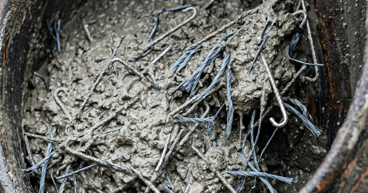
A cracked industrial floor slab six months after pour is one of the most expensive callbacks a contractor can receive, and in the overwhelming majority of cases the root cause traces back to a single design decision made before the first truck of concrete arrived: how crack control was handled. Plain concrete has almost no tensile capacity relative to its compressive strength, so shrinkage stress alone is enough to crack an unreinforced or under-reinforced slab within weeks of placement. Fiber reinforced concrete addresses this by distributing millions of discrete steel, glass, or synthetic fibers throughout the mix, each one bridging microcracks before they can widen into the structural and cosmetic failures that generate warranty claims. This article walks through how each major fiber type — steel, macro synthetic, and alkali-resistant glass — actually works at the mechanism level, where each is the right technical choice, and how dosage and performance are validated against recognized standards. For manufacturers and contractors evaluating a move into construction chemicals product lines, fiber selection is one of the clearest examples of where formulation and materials expertise translates directly into fewer field failures and stronger technical credibility with structural engineers.
How Fiber Bridging Actually Controls Cracking
Fiber reinforcement is frequently misunderstood as a way to prevent concrete from cracking at all, but that is not what it does and not what any recognized design standard claims. Concrete's tensile strength is roughly one-tenth of its compressive strength, so microcracking begins almost immediately once shrinkage or load-induced tensile stress exceeds the matrix's low cracking threshold — this happens in fiber reinforced concrete exactly as it does in plain concrete. What changes is what happens after that first crack forms. Discrete fibers crossing the crack plane transfer tensile stress from one crack face to the other through a combination of fiber-matrix bond and, for deformed or hooked fibers, direct mechanical anchorage, which keeps the crack narrow and prevents it from propagating uncontrolled through the section.
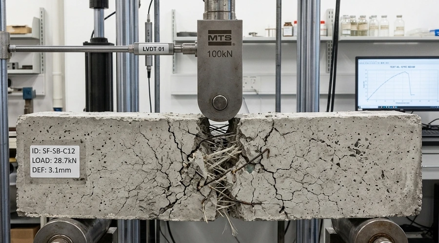
This post-crack load transfer is the entire value proposition of fiber reinforcement, and it is why performance is always reported as a residual strength or toughness value rather than a simple pass/fail crack count. In a standardized flexural beam test, plain concrete fails abruptly at first crack and loses essentially all load-carrying capacity. Adequately dosed fiber reinforced concrete instead continues carrying a meaningful fraction of its peak load well past the cracking point, with the exact residual strength governed by fiber pullout resistance, aspect ratio, anchorage geometry, and dosage rather than matrix strength alone. Understanding this mechanism is the foundation for every subsequent decision about fiber type and dosage — a decision that also interacts directly with the mix design choices covered in our guide to concrete admixture plasticizers and superplasticizers, since fiber-laden mixes typically need more careful workability management.
Steel Fiber Reinforced Concrete (SFRC): Mechanisms and Applications
Steel fiber reinforced concrete is the dominant fiber technology for structural applications requiring high post-crack toughness, and its performance advantage over other fiber types comes almost entirely from mechanical anchorage rather than chemical bond. Modern structural steel fibers are cold-drawn from low-carbon steel wire and formed into hooked-end, crimped, or otherwise deformed geometries specifically so that, once a crack opens and the fiber begins to pull out of the matrix, the deformed ends must physically straighten and plough through the surrounding cement paste before the fiber can fully disengage. This anchorage mechanism gives steel fiber dramatically higher pullout resistance than a straight, smooth filament of the same diameter and length, which is why hooked-end geometry has become the industry-standard design for structural applications.
Steel fiber aspect ratio — length divided by diameter — is a primary design variable, with structural fibers typically in the 45 to 80 range; higher aspect ratios generally improve post-crack toughness but can reduce workability and increase the risk of fiber balling during mixing if not managed with appropriate mix water and admixture adjustments. Steel fiber reinforced concrete is the standard technology for heavy-duty industrial floor slabs, where distributed post-crack strength replaces welded wire mesh under design methods such as the Concrete Society's TR 34 or ACI 360R, as well as for precast tunnel segments and shotcrete ground support in underground construction, where EN 14487-1 and national tunneling codes govern acceptance testing.
| Steel Fiber Geometry | Typical Aspect Ratio | Anchorage Mechanism | Primary Application |
|---|---|---|---|
| Hooked-end | 45–80 | End-hook mechanical anchorage | Industrial slabs, structural SFRC |
| Crimped | 40–65 | Wave-form frictional anchorage | General purpose, shotcrete |
| Straight/smooth | 30–50 | Bond friction only | Crack control, non-structural |
| Deformed/indented | 50–70 | Surface deformation bond | Structural, precast elements |
The trade-off engineers must weigh against steel fiber's superior toughness is corrosion risk at exposed crack faces and surface fibers, and the higher raw material cost relative to synthetic alternatives. Where corrosion exposure is a governing concern — marine structures, chemically aggressive industrial environments, or applications with a hard-troweled exposed finish where surface fiber corrosion staining is cosmetically unacceptable — engineers increasingly specify macro synthetic fiber instead, a substitution decision that leads directly into the next fiber class.
Macro Synthetic Fibers: Polymer Chemistry and Structural Performance
Macro synthetic fibers were developed specifically to close the performance gap between steel fiber's high toughness and microfiber's purely non-structural, plastic-shrinkage-only role, and they now compete directly with steel fiber in slab-on-grade and shotcrete applications where corrosion resistance is the deciding factor. These fibers are extruded from polypropylene, high-density polyethylene, or engineered polymer blends into monofilament or fibrillated (mesh-like) forms at lengths typically between 35 and 60 millimeters — large enough to qualify as macro fiber under ASTM C1116 and EN 14889-2, distinguishing them from the much shorter, thinner microfibers used solely for plastic shrinkage crack control.
Because polymer fibers lack steel's inherent stiffness and rely entirely on surface texture, embossing, or fibrillated structure for anchorage rather than a mechanically deformed hook, achieving comparable residual strength to steel fiber generally requires careful polymer selection and surface engineering during fiber manufacture, validated against the specific product's own EN 14651 or ASTM C1609 test data rather than assumed from generic literature values. The chemistry advantage is substantial, however: polymer fibers are immune to the electrochemical corrosion that threatens steel fiber at cracks and exposed surfaces, they add no risk of surface rust staining on architectural or food-grade floor finishes, and they are non-magnetic and non-conductive, which matters in specialized environments such as data centers or facilities with sensitive electronic equipment.
- Polypropylene monofilament — good chemical resistance, lower modulus of elasticity than steel, requires higher dosage by volume for equivalent toughness
- Fibrillated polypropylene — mesh-like network structure improves mechanical interlock and dispersion uniformity
- Polyolefin blends — engineered copolymer formulations targeting higher tensile modulus and improved matrix bond
- Embossed/deformed monofilament — surface texturing increases pullout resistance without steel's corrosion liability
Glass Fiber Reinforced Concrete (GFRC): Architectural Applications
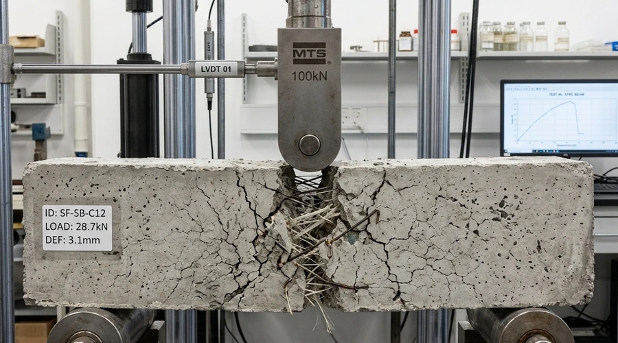
Glass fiber reinforced concrete occupies a fundamentally different application space from steel and macro synthetic fiber: rather than structural crack control in slabs and shotcrete, GFRC is used almost exclusively in thin-cast architectural cladding panels, ornamental facade elements, and precast decorative components where its high early-age strength-to-weight ratio and ability to be cast into complex molded profiles are the priority. GFRC panels are typically only 10 to 20 millimeters thick, far thinner than any steel or macro synthetic fiber application, which is only achievable because glass fiber's fine filament diameter allows very high fiber surface area and reinforcement efficiency in a thin cementitious skin.
The single most important material science fact governing GFRC durability is that ordinary E-glass fiber is unsuitable for use in Portland cement because the cement pore solution's high alkalinity — typically pH 12.5 to 13.5 — attacks and degrades the glass silica network over time, a failure mode documented since GFRC's earliest commercial use in the 1970s. Alkali-resistant (AR) glass fiber, formulated with zirconium dioxide typically at 16 to 20 percent by weight, forms a protective hydration layer that dramatically slows this alkali attack and is the only glass fiber chemistry recognized in current GFRC industry standards. Specifying AR-glass rather than ordinary E-glass is not an optional performance upgrade — it is the baseline requirement for any cementitious glass fiber application, and mistaking this distinction has caused real documented long-term panel failures in the industry's history.
| Property | E-Glass Fiber | AR-Glass Fiber |
|---|---|---|
| Zirconia (ZrO₂) content | ~0% | 16–20% typical |
| Alkaline pore solution resistance | Poor — degrades over months to years | High — protective hydration layer forms |
| Suitability in Portland cement | Not suitable — documented failure mode | Industry standard for GFRC |
| Typical application | Fiberglass composites, insulation | Architectural cladding, precast GFRC panels |
Beyond fiber chemistry, GFRC panel manufacture is a distinct production process from conventional fiber reinforced concrete — typically spray-up or premix processes producing thin sprayed or cast laminate sections rather than fibers dosed into a conventional slump-tested concrete mix — which means GFRC formulation, curing, and quality control expertise is a specialized subset of construction chemicals knowledge, closely related to the polymer-modified systems discussed in our concrete curing compounds guide, since proper early-age moisture curing is equally critical to both technologies.
Selection, Dosage, and Standardized Testing for Fiber Reinforced Concrete
Choosing between steel, macro synthetic, and glass fiber is ultimately a structural design decision driven by the governing failure mode, exposure environment, and cost target of the specific application, not a generic preference for one fiber family over another. Steel fiber remains the default choice where maximum residual strength per unit cost is the priority and corrosion exposure is manageable, such as most interior industrial floor slabs and precast tunnel segments. Macro synthetic fiber is increasingly specified where corrosion risk, magnetic interference, or surface staining on an exposed architectural floor finish rules out steel, while glass fiber serves an entirely separate architectural cladding market where thin-section moldability is the governing requirement rather than post-crack structural toughness.
Whatever fiber type is chosen, dosage must never be estimated from generic published literature values or from a competitor's technical data sheet; it must be established from the specific product's own third-party flexural toughness test data at the proposed dosage rate, translated into a design residual strength class by a structural engineer using recognized guidance such as ACI 360R or the Concrete Society's TR 34 for slabs on grade. The primary standardized test methods are ASTM C1609 and EN 14651, which load a beam specimen to generate a full load-deflection curve capturing both first-crack and residual strength at defined deflection points — the actual engineering design parameters, rather than dosage by weight. ASTM C1550, the round determinate panel test, is widely used for shotcrete and slab applications because its biaxial loading better represents real slab behavior than a uniaxial beam test.
- Define the governing failure mode — shrinkage crack control, structural post-crack toughness, or architectural moldability
- Select fiber family — steel for maximum toughness, macro synthetic for corrosion-free structural performance, AR-glass for thin architectural sections
- Reference third-party flexural test data — ASTM C1609, EN 14651, or ASTM C1550 results for the specific product at the proposed dosage
- Validate mix compatibility — confirm workability, dispersion, and absence of fiber balling in trial batches before full-scale production
- Document performance for the structural engineer of record — residual strength class, not dosage alone, is the design input
Fiber manufacturers and formulation teams entering this market must also account for interaction effects between fiber dosage and admixture systems — high fiber loadings can reduce workability and require adjusted superplasticizer dosing, an interaction best resolved through the same systematic mix-design methodology used for ASTM C1609 compliant products. The technical literature on fiber-reinforced concrete continues to expand as new polymer chemistries and steel fiber geometries reach the market, making rigorous, standards-based performance validation the only reliable basis for product claims in this category.
Frequently Asked Questions
What is the difference between steel fiber, glass fiber, and synthetic fiber reinforced concrete?
How does fiber reinforcement actually control cracking in concrete?
Can fiber reinforcement fully replace conventional steel rebar or welded wire mesh?
Why does alkali-resistant glass fiber matter and what happens if ordinary E-glass fiber is used instead?
What test methods are used to evaluate fiber reinforced concrete performance?
How is fiber dosage determined for a specific concrete application?
When should a construction chemicals formulation consultant be involved in fiber reinforced concrete product development?
Need Construction Chemicals Formulation Support?
Our team provides end-to-end technical consultancy — from fiber and admixture selection to mix design validation, performance testing strategy, and regulatory compliance.
Get a Free Consultation